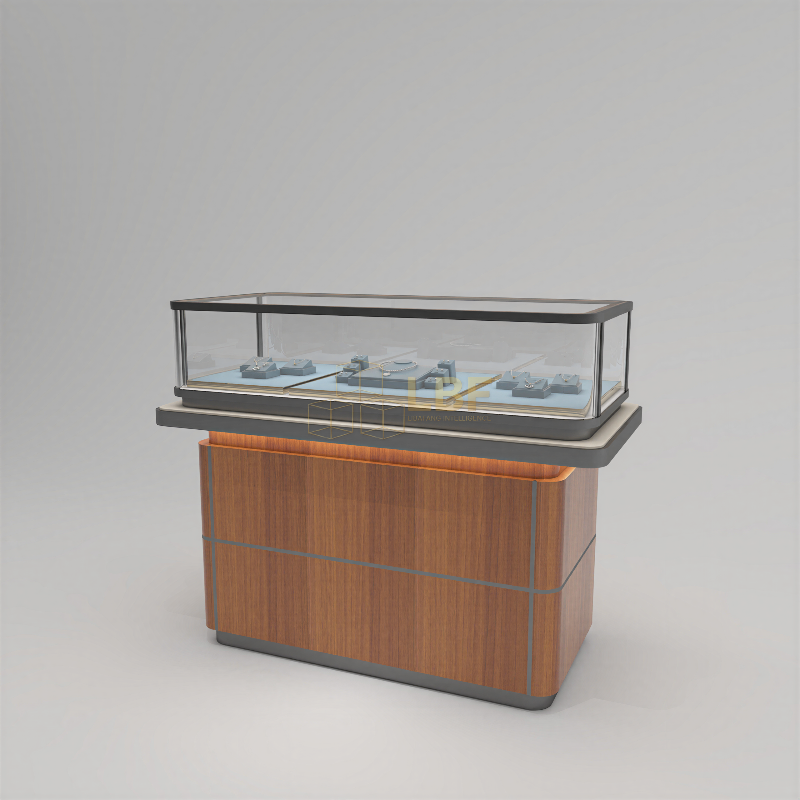

A 2-meter museum display case full of mineral specimens, armor, or dense ceramics can weigh well over 1,000 kg once glass, deck panels, lighting hardware, and an internal base are counted. That load does not disappear into the air. It travels through leveling feet, base rails, or a plinth and into the building’s floor. When floor capacity, flatness, or access routes have not been confirmed early, case delivery days turn into emergency engineering reviews. This guide covers the checks to run with the building team before production drawings are finalized, so installation proceeds without structural surprises.
Start with the real loaded weight, not the empty case weight
Vendors often quote the empty showcase weight, which is almost meaningless for floor loading. To get usable numbers, ask for a loaded weight calculation broken down by component:
- Case structure in aluminum or steel: often 80-250 kg depending on size and glass spec.
- Laminated or low-iron glass panels: 20-40 kg per square meter for 10 mm laminated glass, more for insulated vitrines.
- Internal deck, plinth, and case furniture: 20-100 kg.
- Lighting, climate-control cassettes, and cable trays: 5-30 kg.
- Collection mass: this can be the largest single item and should be estimated by the curator, not the fabricator.
Multiply the loaded weight by 1.5 to 2.0 as an initial design factor for dynamic and uneven loading before any formal structural sign-off. For isolated point loads, divide the share carried by each foot or rail by its contact area. A 400 kg case resting on four feet with 40 mm square pads gives roughly 250 kPa under each pad, which is significant on raised floors and mezzanines.
Establish the floor’s allowable live load before finalizing case design
Museum gallery floors typically support far more than office space, but the figure should come from a structural engineer or the facility’s existing drawings. Common benchmarks: office and gallery space at 2.5-4.0 kN per square meter, storage and heavy artifact areas at 5.0-7.5 kN per square meter, and mezzanine or upper-floor locations often at the lower end. Any case whose footprint load exceeds these values needs a load-spreading plinth, steel base frame, or relocation.
Raised access floors are the most common failure point. Pedestal-supported panels generally carry a concentrated load of 3-5 kN per panel at the pedestal, and that is a panel rating, not a point-load rating for a small case foot placed mid-panel. Cases should always sit over pedestals or on a continuous steel sub-frame, never on the unsupported center of a floor ply. The building team should confirm panel make-up, pedestal grid, and any existing cable penetrations under the case position.
Check floor flatness and leveling range together
Display cases are typically designed with 10-20 mm of leveling adjustment in each foot. Museum specification floors are commonly required at 3 mm deviation over 3 m, but older galleries, polished concrete, and stone finishes frequently exceed that by a factor of two or three. If flatness is outside the case’s leveling capacity, the fabricator must increase foot travel, shims become stackable and unstable, and door alignment suffers.
Request a floor survey of the proposed case positions with deviations recorded on a simple plan grid. Where variation is unavoidable, discuss a continuous adjustable plinth or a self-levelling grout bed with the building team before the case drawings are released. On screens, even a 2 mm twist across a 1.5 m width becomes visible as inconsistency in sliding mechanisms and gaps around glass doors.
Confirm anchoring, seismic requirements, and penetration rules
Anchoring is driven by jurisdiction and building type, not by preference. In seismic zones, tall freestanding cases are usually restrained to the floor with chemical anchors or through-bolted base plates, and older museum buildings with heritage protections may forbid drilling into historic stone or terrazzo. Resolve the following with the building team in one session:
- Which case types must be restrained, and to what acceleration or code reference.
- Whether floor penetrations are allowed, and who repairs finishes afterward.
- Where anchor positions can be placed to avoid post-tensioned cables, embedded conduits, and floor heating.
- Whether wiring for lighting must pass through the floor or up behind the case.
If drilling is not permitted, plan counterweighted bases or wall-tethered restraint with the structural engineer. Retrofitting restraint after the case is on site rarely goes well, as base frames must be re-drilled and glass re-aligned.
Coordinate delivery routes, staging load, and installation windows
The structural review is only half the job. The route from the loading dock to the gallery sets practical limits on case size and weight, and it needs the same early attention. Agree on floor protection across finished surfaces, maximum caster load for pallet jacks and case dollies, door widths, lift capacities, and corridor turns. A common constraint: 500 kg per case dolly wheel on a protected timber floor on the access route, and any stair run or ramp gradient above 5 degrees requiring a crane or lift assist. Staging areas hold stacked crates, so demand temporary floor loads are also checked against the same allowable figures.
Ask the museum’s facilities team about climate and access restrictions too, such as gallery humidity setpoints during glass installation and any periods when the floor must remain free.
Document the assumptions in the project file
Once the numbers are agreed, put them on paper. A one-page coordination sheet listing loaded weights, point loads, allowable floor load, flatness survey results, anchor type and positions, floor protection, and access route prevents disputes later. Review it against the final fabrication drawings before cutting, not after. Suppliers who work with museums regularly, such as Libafang, can supply load calculations and base connection details formatted for structural sign-off, which shortens this round considerably.
Handled in the order above, floor loading coordination adds a few days to the design schedule but rarely adds cost. Handled late, it can mean redesigned bases, rejected deliveries, and unfinished galleries on opening day. If a project is approaching the drawing release stage, gather the loaded weight, flatness survey, and floor load figure first, and everything else follows cleanly.
Planning a museum or gallery installation? Send your case types, locations, and floor data to Libafang for a free design consultation and detailed quote, including loaded weight and base load calculations for your structural team.