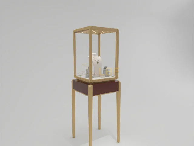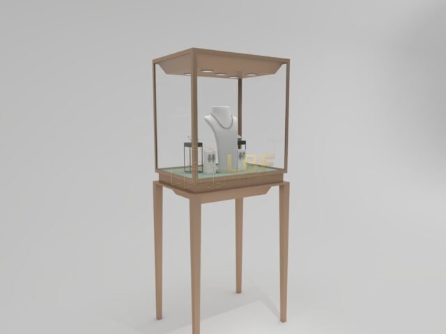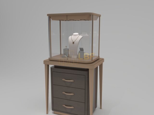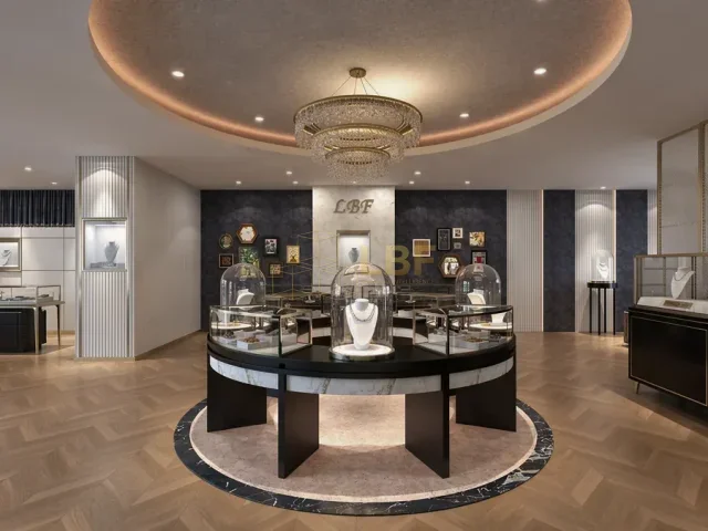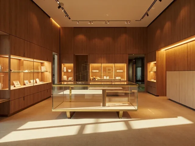

Most museum display case plinths look like simple boxes, but they are the hardest-working part of the case. A plinth carries the object load, hides the lighting driver and environmental control hardware, routes cables, permits leveling on uneven floors, and gives technicians a way in without disturbing the vitrine above. Getting the plinth wrong shows up later as cracked stone tops, jammed access doors, overheating electronics, or a case that cannot be serviced in a crowded gallery. This guide covers the practical planning decisions — compartment sizing, panel construction, tolerances, ventilation and service access — that determine whether a museum display case plinth stays reliable for twenty years. Libafang builds custom plinths for museums and luxury retail in more than 30 countries, and these are the specifications we work through with curators and fabrication teams before cutting any material.
Decide what the plinth must contain before fixing its size
A plinth is a housing first and a pedestal second. Start with a service load schedule: every driver, dimmer, sensor, fan, humidifier cartridge, battery backup and junction box that lives inside, plus future additions. A typical enclosed LED driver is 30 × 120 × 200 mm and dissipates 8–20 W; a small humidity control module may run 200 mm deep. Add 40–50 mm clearance on all sides of powered components and 80–100 mm behind them for cable bend radius. In practice, a display top under 600 × 400 mm usually needs only a shallow 250–300 mm deep cabinet, while a case supporting integrated climate control may need 400–500 mm of internal depth. Plan the plinth footprint 50–80 mm smaller than the vitrine above so the glazing sits proud and the base reads as a shadow line — this also keeps moisture and dust from pooling on the plinth top.
Height, mass and the 900 mm viewing rule
Standard plinth heights sit between 750 mm and 1100 mm measured to the top surface, with 900–950 mm the common compromise for standing visitors and object centers near eye level. Tabletop cases for seated study may drop to 720 mm. Heavier objects lower the top for stability; a 60 kg bronze on a 900 mm plinth behaves very differently from a 2 kg ceramic, and the center of gravity should stay within the middle third of the footprint. Allow for the floor: a 1000 mm plinth on a 20 mm adjustable foot range still needs at least 15 mm of leveling travel on a typical gallery slab. Structural panels of 18 mm birch plywood or 18 mm MDF with a steel chassis handle most loads; stone-clad plinths over 1200 mm tall generally need an internal steel frame to stop the cladding from cracking under racking loads.
Service compartments: layout, doors and tolerances
Service access should be possible without lifting the vitrine, moving the object, or kneeling on a fragile floor. Split the internal volume into zones: a lockable equipment bay, a cable chamber, and a leveling or ballast zone at the base. Keep high-voltage components in a separate metal-lined bay from anything near the object, and mount drivers on a removable tray so they can be swapped without reaching into the case. Hinged doors are easiest for shallow plinths, while sliding or lift-off panels suit tight gallery layouts where a door swing would block a walkway. Specify door gaps of no more than 2 mm for a clean shadow line, use concealed hinges rated for the panel weight, and fit a quarter-turn lock or magnetic catch plus a mechanical safety catch on anything above 400 mm tall. Label every compartment internally with a printed circuit reference so the next technician is not guessing.
- Equipment bay: minimum 300 × 250 × 250 mm clear, metal-lined, with a removable driver tray.
- Cable chamber: 60–80 mm deep vertical channel with 50 mm grommets and a 100 mm floor exit for power and data.
- Leveling zone: 60–100 mm base recess with 4–6 adjustable feet, each rated 250 kg or more.
- Access panels: fixed with captive screws (M5 or M6) or quarter-turn fasteners, never wood screws that strip after two services.
- Documentation pocket: a flat pouch inside the bay for wiring diagrams and a maintenance log.
Removable panels: materials, joints and finish checks
Removable panels are the most-touched component and the most common source of complaints. Use 18 mm panels for plinth sides and 12–18 mm for internal dividers; solid timber moves with humidity and will eventually bind in the frame, so specify stable engineered board or a plywood core with a balanced veneer. Edge joints should be machined with a 1–2 mm reveal rather than a butt joint, which hides inevitable seasonal movement. If the plinth is stone-clad, panels must be removable as complete clad cassettes mounted on hidden clips — never tile individual pieces in place. For painted finishes, ask for an anti-fingerprint matte lacquer at 25–30 gloss units; galleries show marks quickly. Always request a physical mock-up of one removable panel with the final finish before the full run, and confirm the panel returns to a flush fit after 10 removal cycles.
Ventilation, sealing and environmental control
Electronics generate heat, and seal gaskets that protect the object trap that heat inside. Plan for low-level intake and high-level exhaust vents in the equipment bay with a path that never leads into the display volume. A small 40–60 mm fan moving 10–20 m³/h is enough for most driver bays, mounted on rubber isolators to keep acoustic noise below 30 dB(A) at 1 m. If the case uses active humidity control, route the cartridge through a gasketed aperture with a service access point on the plinth, not the deck. Maintain at least a 25 mm gap between the plinth top and the vitrine deck to prevent condensation transfer on stone or glass tops. At the end of commissioning, test with the panels fitted: run the lighting for 4 hours and confirm internal temperatures stay below the driver manufacturer’s rating, typically 40–50 °C ambient.
SEO note for specifiers
When writing a tender or design brief, name the plinth as a distinct assembly with its own drawing set, service schedule and panel schedule. That single change forces the compartment layout, tolerances and access route to be resolved before manufacture, which is where most project risks sit. Libafang can review your object list, lighting load and gallery dimensions and return a dimensioned plinth concept, usually within 3–5 working days, with service compartment and removable panel details built in.
Ready to plan your next case? Send your vitrine sizes, object weights and hardware list to request a free design and quote from our Guangzhou workshop — no obligation, and our engineers will flag any compartment or access issues before you commit.