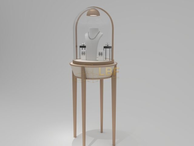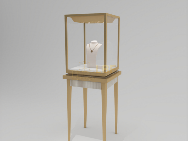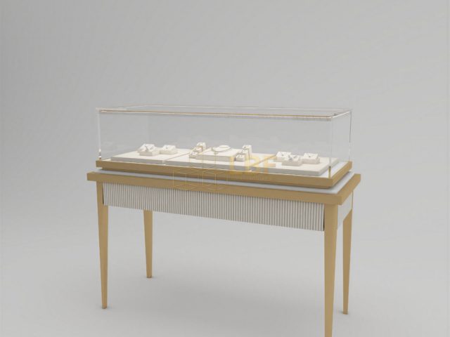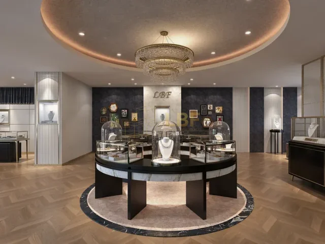

A museum display case is a precision piece of furniture, a climate chamber and a security device at the same time, and the third role is usually the one designed last. That matters because alarm integration is the failure point where otherwise excellent casework gets held up on site: the magnetic contact sits 4 mm too far from the door frame, the cable has no route that survives 200 door cycles, or the installer cannot reach the terminal block without removing a 40 kg glass hood. Museum display case alarm integration works when three things are settled before fabrication drawing release: the contact type and its mounting geometry, the cable path with real tolerance, and how a technician will service the electronics for the next 15 years. This guide covers each in practical terms.
Choose contacts by door behaviour, not by catalogue convenience
Most museum cases use swinging or sliding glass doors, removable hoods, or lift-off vitrines, and each behaves differently under a reed switch. For a hinged door, a recessed or surface-mounted reed contact with 15 to 25 mm operating gap is the default; align it on the hinge side of the opening where movement is smallest, not the free edge where frame flex at a 90 degree open position can add 2 to 3 mm of drift. For sliding doors, prefer a balanced or biased reed pair that tolerates lateral travel of 10 mm or more, because guides wear and the door rarely returns to the same millimetres after a year of docent use. Removable hoods and lift-off segments need either a plunger-style contact or a magnetic transfer that registers full removal rather than a change in gap, since a hood lifted straight up can keep a reed closed.
Two specifications are often missed in the case schedule. First, contact rating versus loop characteristics: a typical balanced loop carries 1 to 10 mA at 12 to 24 VDC, so specify contacts rated for low-level signals with gold-plated or rhodium contacts to avoid film build-up over years of near-zero current. Second, addressability. If the site uses addressable modules or a bus, confirm whether each case is its own zone or several doors share one. Per-case zoning looks tidy on drawings, but a 40-case gallery produces 40 panel addresses and an unwieldy alarm response procedure; 4 to 8 doors per zone is a common compromise, grouped by room or wall.
Route cables with the mechanic, not against it
Armoured or shielded cabling rated for the loop’s voltage and the case’s fire classification is the baseline. What determines whether the integration works long-term is the path. Cable must leave the case through a glanded, grommeted exit — not over a raw metal edge — and be given a service loop of at least 150 mm at every hinge or articulated joint. In hinged-door cases the highest-wear cable is the door cord between frame and leaf; specify a coiled or high-flex cord with a rated bend life above 100,000 cycles, and route it so it never pinches in the closer or passes through the gloves’ reach area.
For floor-level routing, keep the first 200 mm of drop inside the case’s own footprint so cleaning crews and scissor lifts cannot pull the cable. In showcases built for touring exhibitions, every internal cable should be a discrete connector, not a splice, so that a case can be packed and reassembled without re-termination on a gallery floor. Shielded, twisted-pair cable is a sensible default where cases sit within a metre of LED drivers: switching noise from dimmable drivers is a common source of nuisance and re-opening zones, and 300 mm of physical separation between the driver’s mains wiring and the alarm loop often costs nothing at design stage but is impossible to retro-fit later.
Design service access as a first-class requirement
The single most expensive integration error is a terminal block reachable only by two people and a glass lifter. Put electronics in a dedicated, tool-locked equipment drawer or lockable base compartment with a minimum 250 mm clear access width and a visible wiring diagram laminated inside. The following checklist is a practical basis for case specification:
- Every contact, splice and resistor is serviceable with the case closed and alarm-armed bypass in place.
- Component access reaching at least 90 percent of terminals without moving glass panels or hoods over 15 kg.
- A labelled, fused loop terminal for incoming field wiring at a height of 400 to 900 mm.
- Cord grip or cable management that leaves at least 150 mm of slack with the cable not under tension.
- Test points or a status indicator usable without opening the lockable compartment door.
Service access also affects the museum’s own operation: cases adjacent to fire exits must be serviceable without blocking egress, and in libraries and archives the drawer needs to open fully in front of shelving, which should be checked against the case elevation drawings, not left to commissioning.
Coordinate drawings and commissioning across three parties
Alarm contacts reach the case on the integrator’s RFI, but the case manufacturer owns the hole. Exchange dimensioned details early: contact centre height, mounting screw centres, pocket depth (a minimum of 12 to 15 mm is usual for recessed types, with the cable pocket wide enough for a 6 mm trunk), and the cable entry position from the underside in a top plan drawing. Furniture, casework and security should sign off on a single interface drawing at 1:20 for each case family and a typical 1:50 gallery plan for routing. At FAT or delivery inspection, test every door and hood as wired: a 10-test cycle of open, closed and full override finds more than site commissioning ever will. Allow two to three days of security commissioning per 20 to 30 cases plus spares, and carry a labelled contact of each type in your spares kit.
Libafang works to this integration approach as standard for museums and gallery projects, providing access panels, internal cable glands and flexible door cords to the integrator’s schedule where supplied. Getting it right is mostly a matter of taking the case’s security role as seriously as its glass.
If you are planning a gallery refit, share your alarm zone plan and door details with us and request a free design and quote — we will return dimensioned drawings showing contact positions, cable entries and service-panel locations for your integrator’s approval.